Edges
Overview
This file describes the Edges object.
It contains the core information required to describe the edges
of each slit on a given detector (or orders for echelle).
See below for the Current EdgeTrace Data Model.
This is written to disk as a multi-extension FITS file prefixed by
Edges in the Calibrations/ folder.
See the Calibration Frame Naming docs for more.
We also describe how to view the slit edges using pypeit_chk_edges.
Viewing
The preferred way to view the slit edges identified by PypeIt is with the pypeit_chk_edges script.
The script usage can be displayed by calling the script with the
-h option:
$ pypeit_chk_edges -h
usage: pypeit_chk_edges [-h] [-v VERBOSITY] [--log_file LOG_FILE]
                        [--log_level LOG_LEVEL] [--slits_file SLITS_FILE]
                        [--mpl] [--try_old]
                        trace_file

Display trace image and edge traces

positional arguments:
  trace_file            PypeIt Edges file [e.g. Edges_A_0_DET01.fits.gz]

options:
  -h, --help            show this help message and exit
  -v, --verbosity VERBOSITY
                        Verbosity level, which must be 0, 1, or 2. Level 0
                        includes warning and error messages, level 1 adds
                        informational messages, and level 2 adds debugging
                        messages and the calling sequence. (default: 2)
  --log_file LOG_FILE   Name for the log file. If set to "default", a default
                        name is used. If None, a log file is not produced.
                        (default: None)
  --log_level LOG_LEVEL
                        Verbosity level for the log file. If a log file is
                        produce and this is None, the file log will match the
                        console stream log. (default: None)
  --slits_file SLITS_FILE
                        PypeIt Slits file [e.g. Slits_A_1_01.fits]. If this file
                        does not exist or is not provided, PypeIt will attempt
                        to read the default file name (in the Calibrations
                        directory). Ignored if plotting using a matplotlib
                        window instead of ginga. (default: None)
  --mpl                 Use a matplotlib window instead of ginga to show the
                        trace (default: False)
  --try_old             Attempt to load old datamodel versions. A crash may
                        ensue.. (default: False)
pypeit_chk_edges
There are currently 2 options for viewing the slit edges on the image used to construct them. Each uses the pypeit_chk_edges script.
ginga
This is the default mode when executing, e.g.:
pypeit_chk_edges Calibrations/Edges_A_1_DET01.fits.gz
Warning
These files can take an annoyingly long time to load because they tend to be large and require decompression.
Two images are shown, the trace image (typically a combination of dome flats) and the Sobel filtered image used to detect the slit edges.
Here is a zoom-in screen shot for the LRIS RED spectrograph.
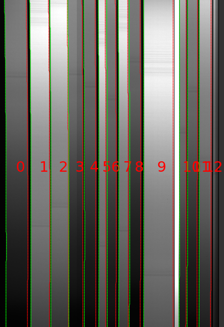
A few things to note from this good-performing example:
The slits run nearly vertically across the image
The left/right edge of each slit identified is a green/red (purple in more recent versions) line
There were 13 slits identified (0 indexing)
The brightest slit is an alignment box and was discarded by the code
matplotlib
To avoid ginga, use the –mpl flag:
pypeit_chk_edges Calibrations/Edges_A_1_DET01.fits.gz --mpl
The color scheme is distinct and the labeling now includes -1 or +1 for left/right edges.
SlitTrace
The Edges file allows one to fully reconstruct its underlying object
(EdgeTraceSet) when instantiated from the output
file. Unfortunately, this means the PypeIt object and output file are a bit too
unwieldy to pass through the remainder of the code just to access its primary
product, the slit-edge pixel coordinates. For that reason, we also create a
Slits object; follow the link for more description of that object.
Edges Troubleshooting
See Slit Tracing for a discussion of how to customize, debug, and finesse your slit tracing results.
Current EdgeTrace Data Model
Internally, the processed image is held in EdgeTraceSet,
which subclasses from DataContainer.
The datamodel written to disk is:
Version 1.0.1
HDU Name |
HDU Type |
Data Type |
Description |
|---|---|---|---|
|
… |
Empty data HDU. Contains basic header information. |
|
|
… |
… |
Image used to construct the edge traces; see |
… |
… |
… |
… |
|
uint8 |
Bad-pixel mask for trace image |
|
|
float32 |
Sobel-filtered image used to detect edges |
|
|
int64 |
ID number for the edge traces. Negative and positive IDs are for, respectively, left and right edges. |
|
|
int64 |
slitmask ID number for the edge traces. IDs are for, respectively, left and right edges. Only defined if mask-design metadata is available. |
|
|
float32 |
(Floating-point) Measured spatial coordinate of the edge traces for each spectral pixel. Shape is (Nspec,Ntrace). |
|
|
float32 |
Error in the measured spatial coordinate edge traces. |
|
|
int32 |
Bitmask for the edge trace positions. |
|
|
float32 |
The best-fit model result for the trace edge. |
|
|
… |
The PCA decomposition of all edge traces. Not defined if PCA separated between left and right traces (i.e., the left_right_pca parameter is True). See |
|
|
… |
Model parameters for the ?th component of the PCA; see |
|
… |
… |
… |
… |
|
… |
The PCA decomposition of the left-edge traces. Not defined if PCA performed on all traces, regardless of edge side (i.e., the left_right_pca parameter is False). See |
|
|
… |
Model parameters for the ?th component of the left-edge PCA; see |
|
… |
… |
… |
… |
|
… |
The PCA decomposition of the right-edge traces. Not defined if PCA performed on all traces, regardless of edge side (i.e., the left_right_pca parameter is False). See |
|
|
… |
Model parameters for the ?th component of the right-edge PCA; see |
|
… |
… |
… |
… |